Hardware Assembly
Attention
The installation steps are expected to take 30~60 minutes, please note the following:
1.When fixing the screws, do not tighten the screws vigorously to avoid sliding wire;
2.When fixing the board, please tighten them separately after the four copper pillars or screws are fixed;
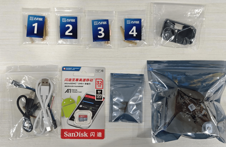
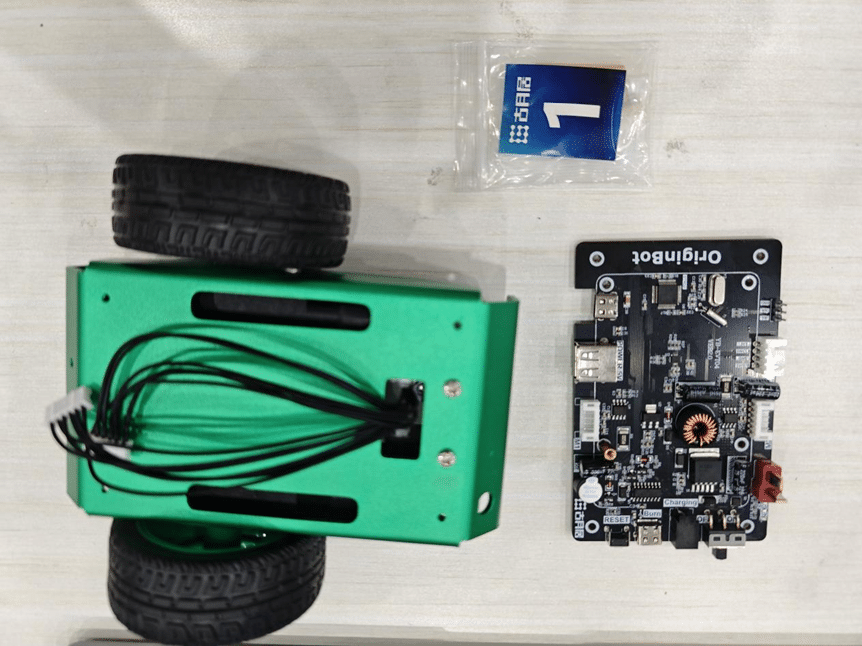
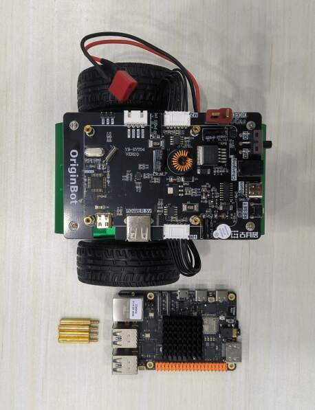
All robot parts
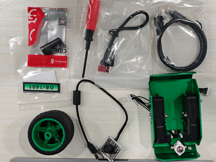
Note
Power supply can refer to Resources Link
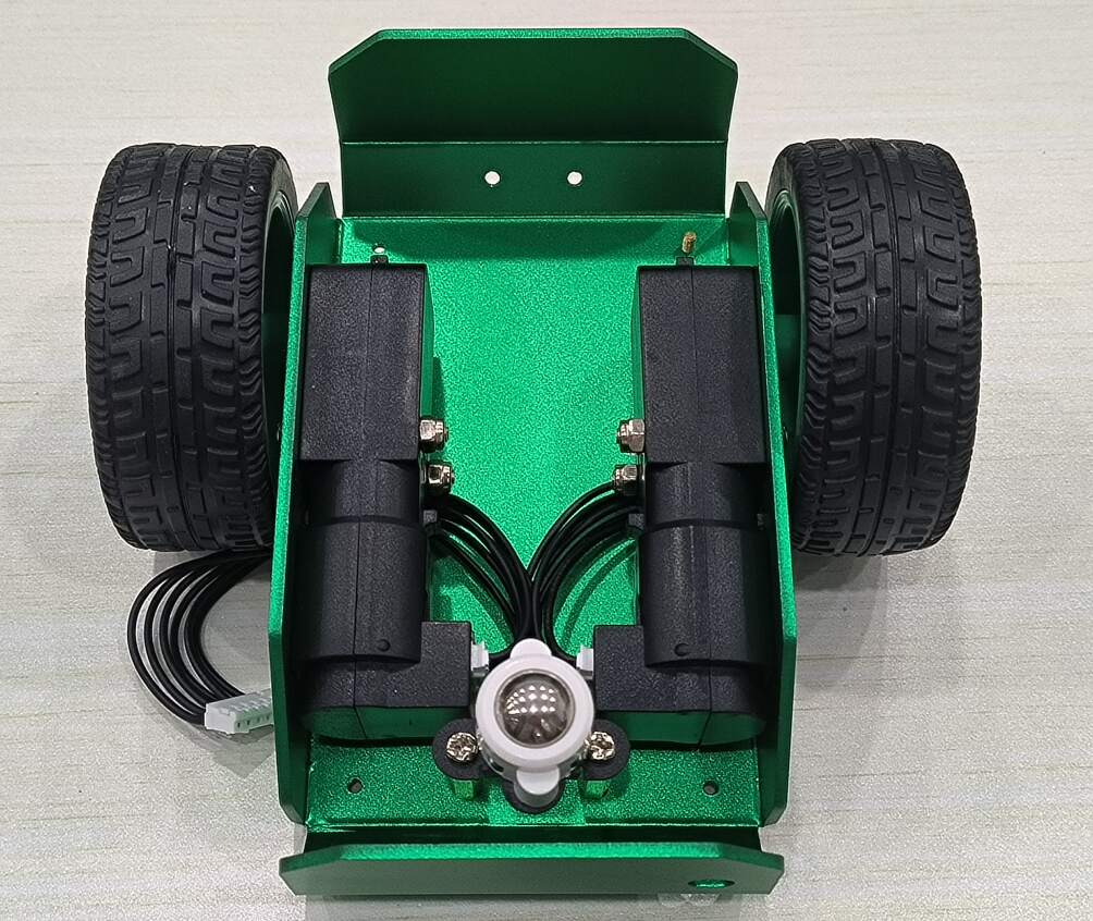
Take out the robot chassis
Install the universal wheels:
The robot chassis has been installed with universal wheels and motors.
Installing the controller board
Install the upper support copper column of the controller Materials Required:
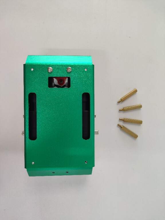
The fixing holes of the chassis have their own threads, and the four copper pillars can be tightened directly

Installing the controller board Materials Required:
You can fix the power supply between the chassis and the control board, but the power supply size cannot exceed 90x70x30mm
Note
Power supply can refer to Resources Link
Use screws to fix the controller to the four supporting copper pillars of the chassis, and connect the motor wires that were previously passed through to the corresponding ports of the controller:
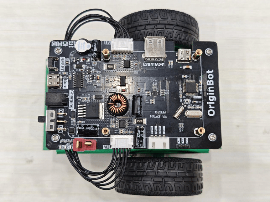
Hint
1.Pay attention to the motor interface serial number. The left motor is connected to the left interface, and the right motor is connected to the right interface. 2.When inserting the white port, it is recommended to press the interface on the controller end with your other hand to avoid lifting it with excessive force; 3.Do not connect the battery power cable at this time to avoid subsequent misoperation;
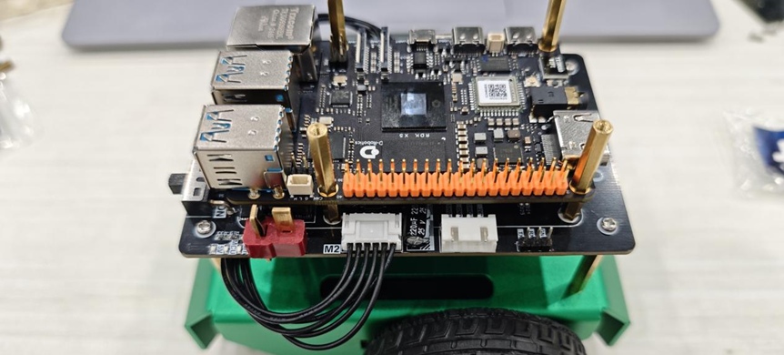
Installing the Processor Board
Installing the Processor Board
Materials Required:
Take out the No.4 screw pack and RDK X5,The RDK X5 can be screwed directly onto the support copper pillar on the controller
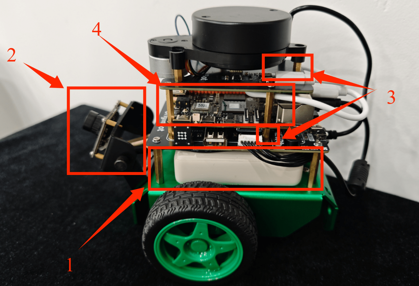
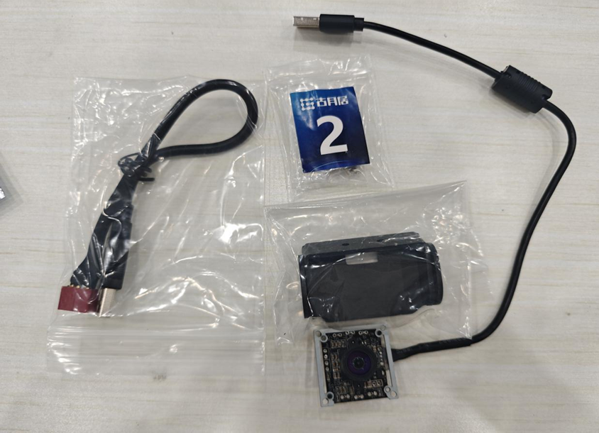
Mounting the Camera
Installing the Camera Module
Materials Required:
Take out the camera, bracket and No. 2 screw bag
Take out the 4 thin copper pillars and install them on the bottom plate of the bracket respectively, then fix the camera on the copper pillar, fix the lower bracket on the bottom shell of the trolley, and fix the two brackets with hand screws
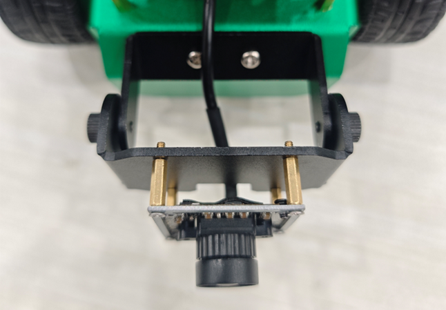
Connect the camera data cable
Pass the camera's USB cable through the chassis controller and the battery, and connect it to the port on the RDK X5:
Danger
Do not unplug or plug the camera cable when the power is on, as this will damage the camera.
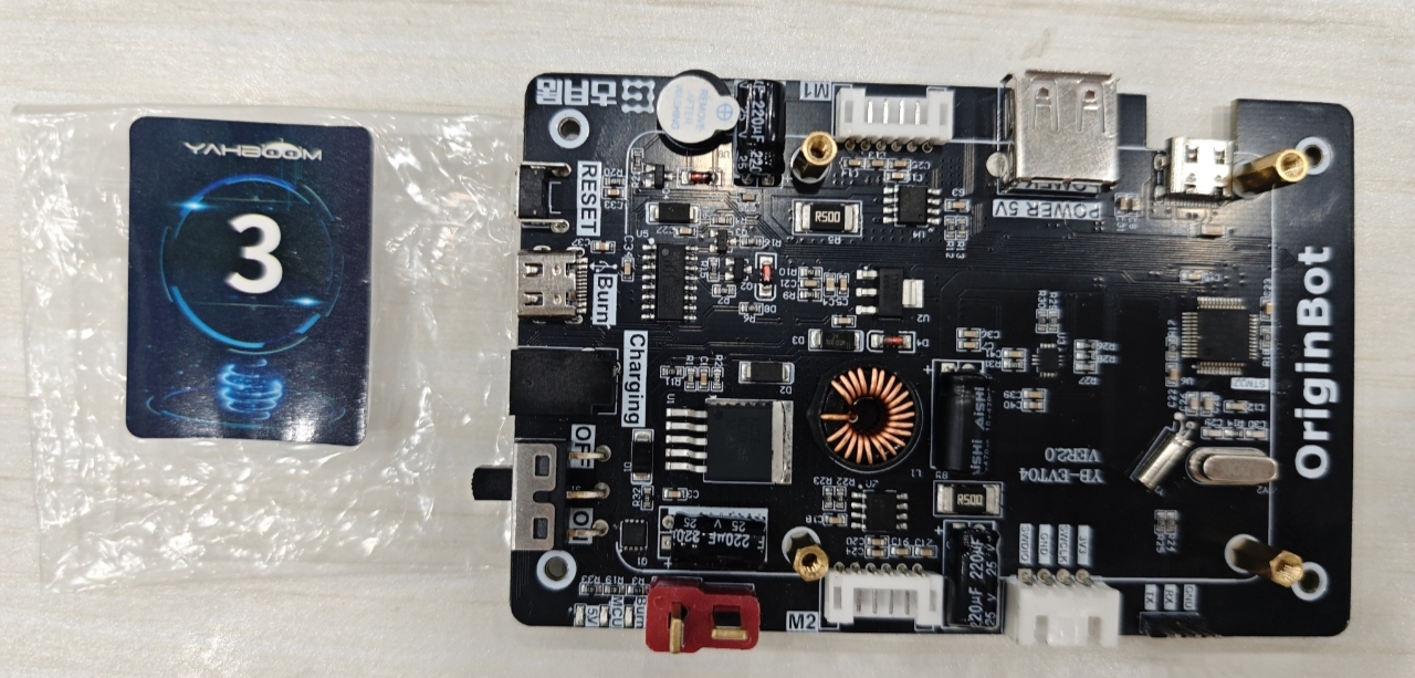
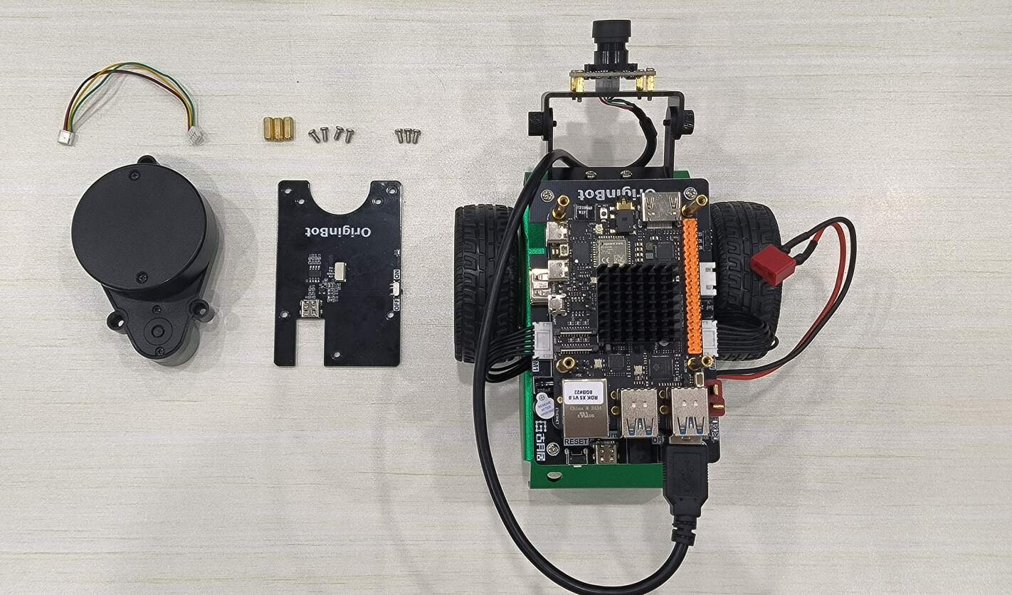
Install lidar
Materials required:
Use the No.3 screw pack
Pass the three copper pillars through the corresponding holes on the radar driver board, fix the other side with three screws, tighten the copper pillars, and connect the radar serial port cable:
Use four screws to fix the radar driver board to the supporting copper column of the car.Connect the other end of the serial cable to the radar:
Install the radar and use three screws to fix the radar to the supporting copper pillars of the radar driver board:
Connect the cables
Materials required:
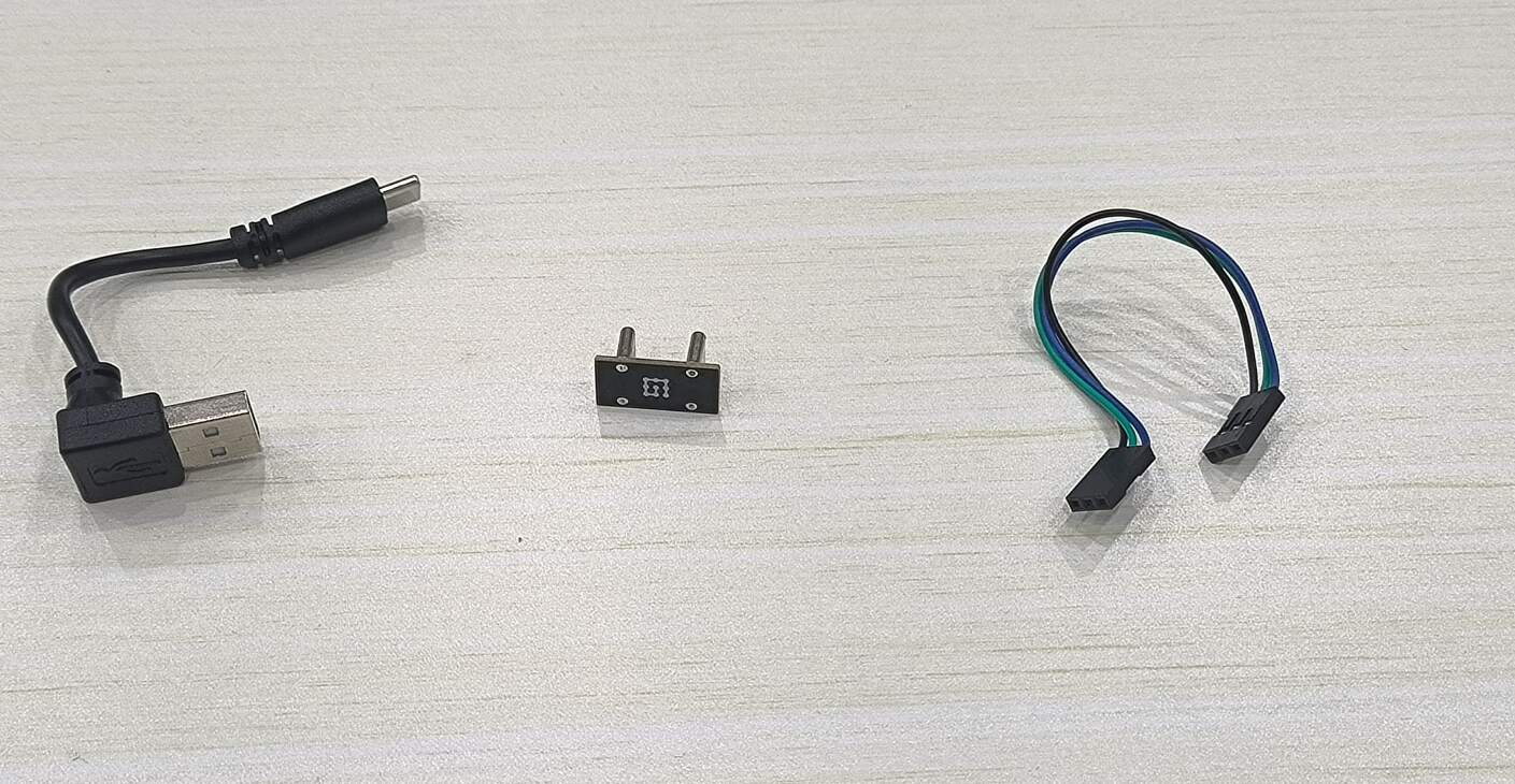
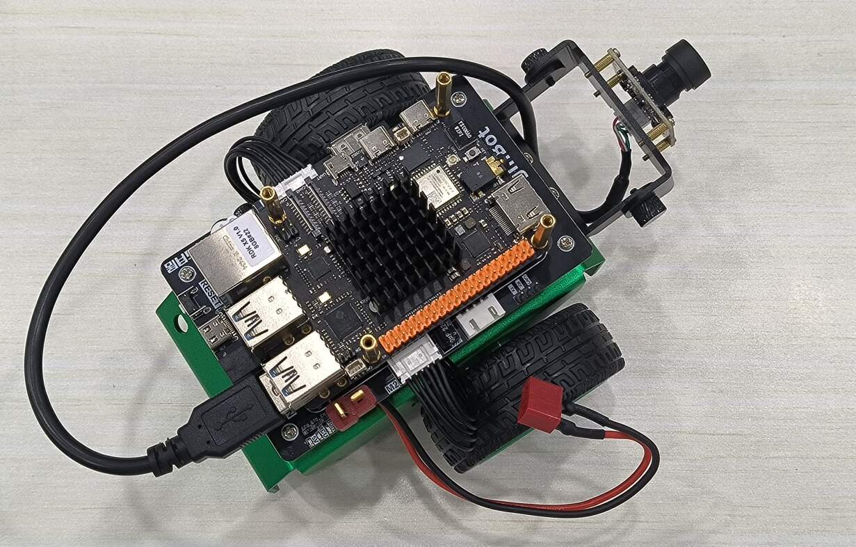
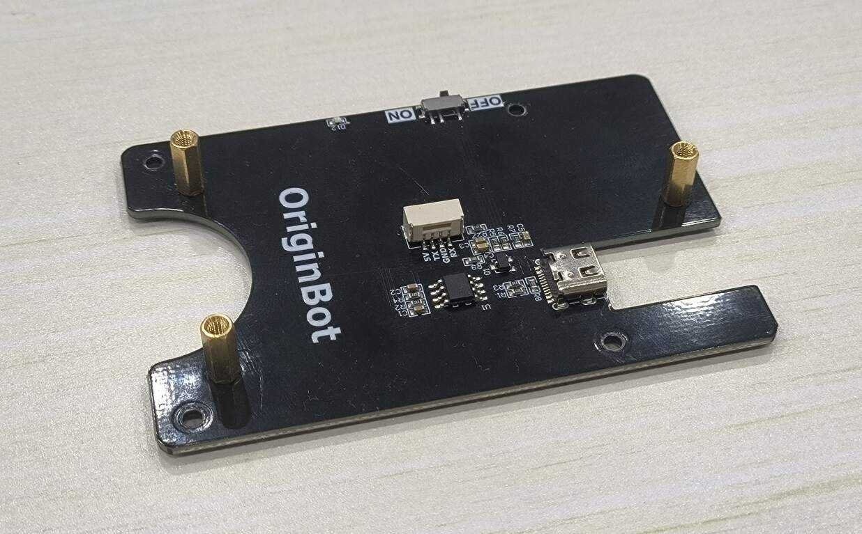
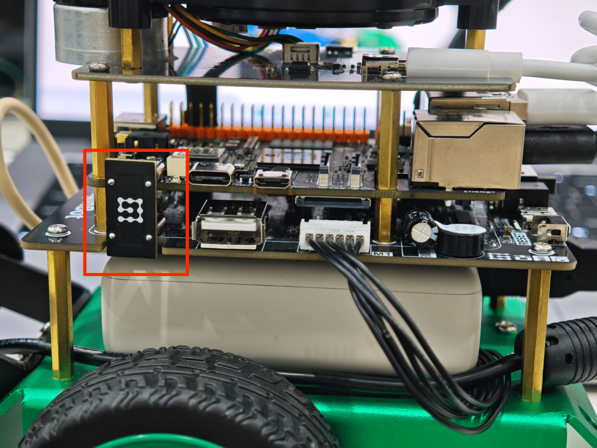
Connect the power supply module RDK X5 is powered by the controller through the Type C port. Use the Type C power supply module to connect the power output of the controller and the power input of the motherboard:
Hint
When plugging or unplugging the Type-C power module, be careful to avoid damaging the SMD pins.
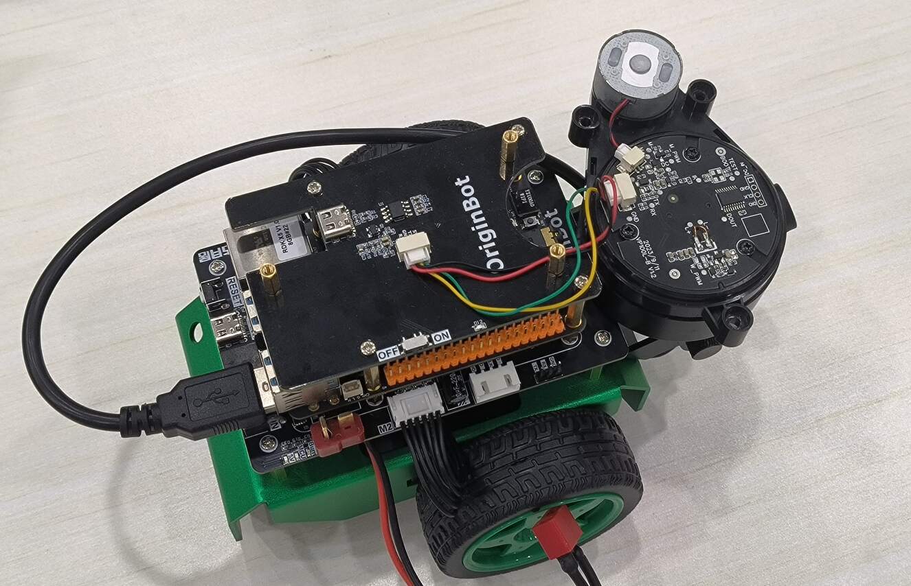
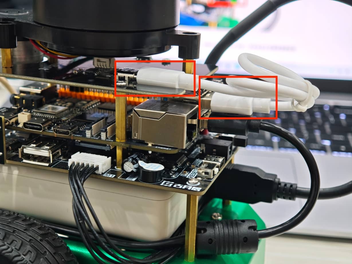
Connect the serial communication line
Use a serial communication cable to connect the controller and the communication interface of RDK X5:
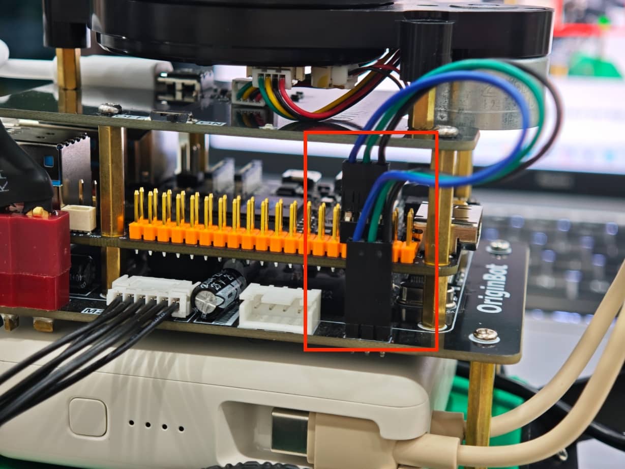
Hint
Please pay attention to the wiring sequence, TX-RX, RX-TX, GND-GND;
Connect the radar communication line
The original Type C data cable of the radar is long. You can use the short cable in the kit. One side is connected to the USB port of RDK X5, and the other side is connected to the Type C port of the radar serial port module:
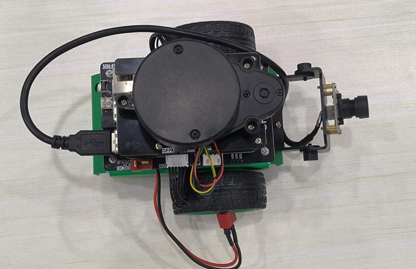
Connect the main power cord
Check that all parts of the robot have been correctly installed according to the operating steps, and the control switch is in the "OFF" state, and connect the main power line of the battery to the controller:
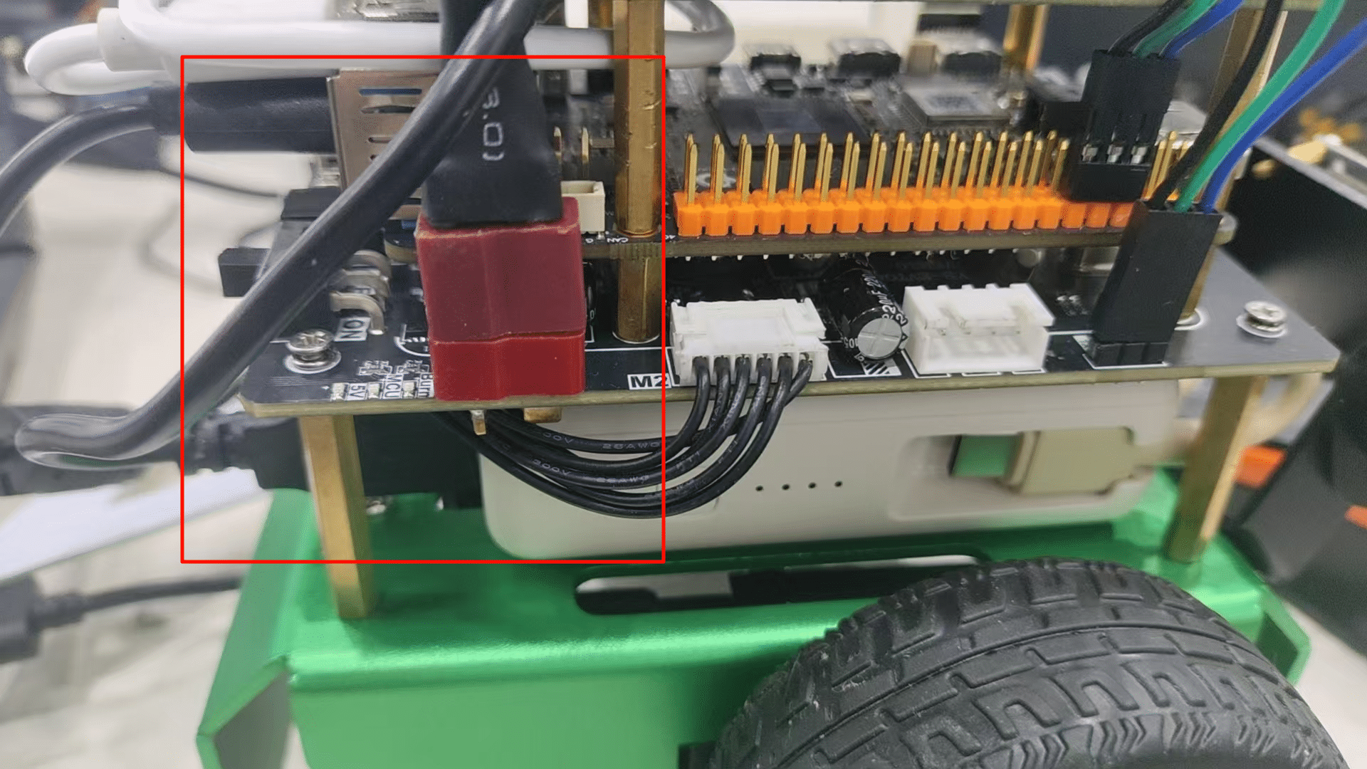
Hint
The power socket is tight and close to the RDK X5, so be careful when installing and inserting it. It will be easier to insert if the two flat parts of the T-shaped plug are close to the socket.
Installing a license plate (optional)
Paste license plate Affix the unique numbered stickers included in the kit to the front and rear sides of the chassis as desired.
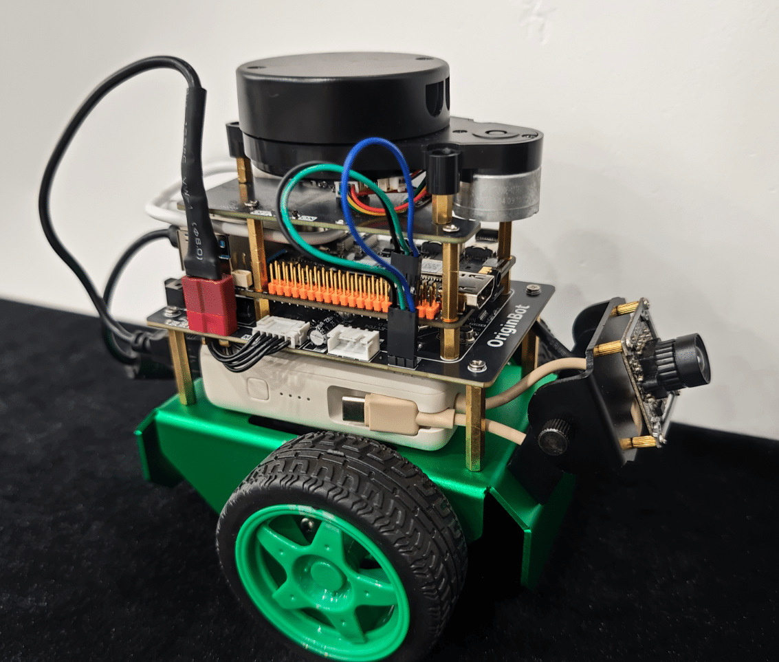
At this point, the OriginBot installation is complete.